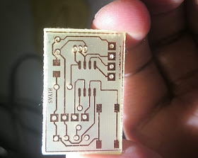
Here is a simple project based on Attiny13a ( which is limited with 1kb flash and 64bytes of SRAM). In this project a simple sensor node is made out of this and collects data from a digital temperature sensor (ds18b20) and the ambient light with an ldr and converted by the ADC(analogue to digital converter) inside the attiny13a.
 |
| Wireless sensor in a transparent tic -tac box to measure light/temperature. It takes 10 micro amps when idle and around 7 milli amps when transmitting. It transmits data in every 16 minutes intervals |
All collected data is send to the receiver via wireless link based on 433mhz OOK modules which needs a protocol to send the data (unlike the dedicated wireless chips with built in protocols and error corrections)
The wireless data is captured in a clock with seven segment led display and a serial connector to send the data to a raspberry pi for further processing.
 |
| Example data received from the sensor |
 |
| data received from the wireless sensor. Top plot is outside temperature and the bottom one is the light intensity |
 |
| Attiny13 based wireless sensor prototype |
Currently at the receive end an atmega328p is used and the result is displayed via serial terminal. But this can be converted in to an oled display/lcd display. More on this and uploading the data to a cloud service and doing analysis on a next post.
The idea of this project is to build from scratch (as far as possible) and use minimalist devices to achieve maximum outcome. I didn't choose assembler, but did the firmware in C and takes exactly 1024 bytes.(This can be the next exercise to free up more space). Within this 1024 bytes , the firmware handles the one wire protocol, reading the ADC, power saving routines and a watchdog timer, and a wireless protocol (borrowed from virtual wire with CRC checksum). The code can be further improved to add some more extras. A small pcb is made which can be used for pro-typing alternate projects such as rolling code remote, wireless water tank overflow detection/pump control etc)
Hardware
The prototype is built on a 2 X 3cm pcb , home etched (details below) and has an sop (attiny13) some connectors and ldr, ds18b20, some pull-up resistors. |
| Schematic for the transmitter prototype. The diagram is missing a 10k pull up resistor for the data pin for the one wire thermometer (ds18b20) |
The rf module used is shown below with a simple wire antenna
Firmware
The software and the source can be downloaded from the github here. It needs avr-gcc to compile and use avrdude to upload to the chips using an isp programmer. you may use an arduino uno as an isp programmer. There is a make file and all you need to do is type inmake flash
Building from scratch
1) PCB - can be made using a presensitised board (e.g Bungard) or toner transfer. |
| A simple one side PCB for the prototype board |
All cad files can be downloaded from the project page on github.
A few pictures from my prototype is shown below
step 1) making a layout
 |
| PCB layout (step 1) |
Step 2) uv exposure (home made with uv led)
3) Developing (bungard)
4) Etched board (ferric chloride)
5) Applying solder mask
6) Assembling
Firmware (main routine in tx)
#include <avr/io.h>
#include <util/delay.h>
#include <avr/interrupt.h>
#include <string.h>
#include "virtualwire.h"
#include <avr/sleep.h>
#include <avr/wdt.h>
#define DS18B20_PIN PB4
#define BUTTON_PIN PB2
// CHANGE IN TX LIBRARY FILE IF CHANGED
#define LDRPIN PB3
#define LEDPIN PB1

typedef struct messagedata
{
 unsigned char RX_ID;
 unsigned int temperature;
 unsigned int light;
 unsigned char button;
} messagedata;
messagedata txdata={.RX_ID='A',.temperature=25,.light='L',.button='L'};

// watchdog interrupt
ISR(WDT_vect)
  {
  wdt_disable();  // disable watchdog
  }

static  void myWatchdogEnable()
{
  cli();
  MCUSR = 0;                          // reset various flags
  //set timer to 1 sec
  //WDTCR |= (0<<WDP3) | (1<<WDP2) | (1<<WDP1) | (0<<WDP0);
  //set timer to 8 sec
  WDTCR |= (1<<WDP3) | (0<<WDP2) | (0<<WDP1) | (1<<WDP0);
  WDTCR |= (1<<WDTIE);
  WDTCR |= (0<<WDE);
  sei();
  wdt_reset(); //call to this reset the timer
  set_sleep_mode (SLEEP_MODE_PWR_DOWN);
  sleep_mode();            // now goes to Sleep and waits for the interrupt
}


int main(void)
{
 DDRB &=~(1<<LDRPIN); //ADC0 is input PB5
    uint16_t nticks=37; // number of prescaled ticks needed TRY 150
    uint8_t prescaler=2;; // Bit values for CS0[2:0] TRY 1
    TCCR0A = 0;
    TCCR0A = _BV(WGM01); // Turn on CTC mode / Output Compare pins disconnected
    TCCR0B = 0;
    TCCR0B = prescaler; // set CS00, CS01, CS02 (other bits not needed)
 OCR0A = (uint8_t)(nticks);
 TIMSK0 |= _BV(OCIE0A);
 vw_ddr |= (1<<vw_tx_pin);
 vw_port &= ~(1<<vw_tx_pin);
 uint16_t t;
    uint8_t rcvdSize = sizeof(txdata);
 // Set the ADC input to PB3 or ADC3
    ADMUX |= (1 << MUX0);
 ADMUX |= (1 << MUX1);
    ADMUX |= (1 << ADLAR);
    ADCSRA |= (1 << ADPS1) | (1 << ADPS0) | (1 << ADEN);
    sei();

    while (1)
    {
  t=DS18B20_read();
  txdata.temperature=t;
  //t = adc_read();
  ADCSRA |= (1 << ADSC);//start conversion
  while (ADCSRA & (1 << ADSC));
  txdata.light=ADC;
  uint8_t counter=9;
  while(counter)
  {
   vw_send((uint8_t *)&txdata, rcvdSize);
   vw_wait_tx();
   _delay_ms(500);
   counter--;
  }
  ADCSRA &= ~(1<<ADEN);     //turn off ADC
        ACSR |= _BV(ACD);         // disable analog comparator
  counter=120;
  while(counter)
  {
   myWatchdogEnable ();  // 8 seconds
   counter--;
  }
  ADCSRA |= (1<<ADEN);    //turn on ADC
    }
}


No comments:
Post a Comment