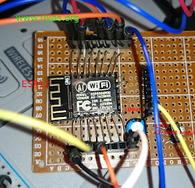
ESP8266 is an extremely popular module among hobbyists for building inexpensive and powerful internet connected projects. The module can connect to a wifi access point and can exchange data. It can act as a wifi access point and can be used to control devices. The GPIO pins on the module can be used for automation and much more (SPI, I2C, I2S).
This post is a log of my quick and dirty test for a fresh bare module from AI-THINKER +25dBm (with 16+6 pins) as shown below
 |
| ESP12 module from AI THINKER |
To test this we need the following things
1) The module works on 3.3 volt and minimum 300ma (while wifi is active, it draws more current, so needs a regulator 1117 or a battery ( 3-3.4 volt is fine) ). I used a simple regulator as shown below to use the 5 volt supply
 |
| ESP12 power supply |
2) USB to the Serial module for communicating from the PC to esp8266 ( i used a cp2102). The RX pin goes to TXD on esp module and vice versa. The ground pin on the usb the o serial module should be connected to ground oin on esp module. This boards rx and tx pins are 3.3 v ( make sure of this, otherwise you need a level shifter)
 |
| usb to serial based on CP2102 |
3) A bit of soldering to add some legs to the module. See figures to sort out how i did in my test to make a simple protoboard
 |
| Adding legs to esp12 using some waste leads from resistors |
ESP module with leads soldered loks like the one below. The extra six on one side can be avoided as it is for internal eeprom and not necessary for most of the uses
 |
| ESP12 "spider" |
The next is keep it on a prototyping board. in addition i placed the regulator (3.3v)and a capacitor (100uF) fromm vcc to ground. Added some sockets for easy access
 |
| A simple ESP12 prototype |
ESP12 pin connections
The pins on esp12 are arranged as shown below
 |
| ESP12 pins layout |
A more useful pin layout is shown below with different pins and their roles (some pins have multiple roles)
 |
| ESP12 pin layout, image courtsey: github.com/esp8266 |
First test of esp12 module
Connect the module to the powersupply (3.3volt) and make sure the module is connected as shown below
 |
| ESP12 quick test circuit with a usb to serial module |
Set the serial monitor as shown below ( 115200 baud rate)
 |
| See serial settings, baud rate 115200, Both NL & CR |
Now leave the GPIO0 unconnected ( see diagram above) and open the serial port. Briefly touch the reset to ground (may use a push to on switch). Serial should show some garbage as below and some messages
 |
| AI thinker serial messages from ESP12 module |
Now you could use some of the AT commands to see the modules factory firmware features (basic wifi access over serial). Just type AT and press enter
 |
| AT mode on ESP12 |
If this is working you could try various AT commands to see the results. But basically it shows your module is working fine and it is better to update the firmware to something else which does a lot more useful things than At commands and wifi over serial port. There are several ways and if you are an arduino user, i would recommend it as it is much simple and easier.
 |
| Common AT commands for esp12 (click to enlarge) |
For teaching kids and for simple usage there are some firmwares like ESP8266 basic (very easy) and other useful ones are MICROPYTHON, NODEMCU. All these can help to establish internet connected projects in a simple and easy manner.
NOTE: One of the main challenge here is the proper wiring and gpio pin connections needed to put the module in to different modes. (e.g BOOT MODE). If it is in wrong mode you wont be able to see anything. Keeping the serial port on and resetting the module should show some garbages on the serial port of anormal working module.
GPIO modes:
0 Low
1 High
x floating
GPIO modes:
0 Low
1 High
x floating
| MODE | GPIO15 | GPIO0 | GPIO2 |
|---|---|---|---|
| SDIO (BootSDCard) | 1 | x | x |
| UART (UploadCode) | 0 | 0 | x or 1 |
| FLASH (NormalRunning) | 0 | 1 | x or 1 |
Restoring the ESP8266 module to the factory firmware with AT mode (Restore AT commands on an esp8266 module)
This can be done by restoring the factory firmware. We use esptool.py to do this and flash the factory firmware from AI thinker.
To do this just download this script. Then run /bin/bash factory_reset.sh in a terminal. This works on a debian/ubuntu based systems. In other cases just go through the commands and install esptool.py and run the following command (Download firmware)
esptool.py --port /dev/ttyUSB0 write_flash -fm dio 0x00000 ai-thinker-v1.1.1.bin
asdsad
ReplyDelete