Safety Considerations
Controlling DC motors at 12 volt with Speed controle (PWM)
Controlling DC motors with PWM (pulse width modulation, to control the intensity/speed) is straight forward. Here we use a special transistor (TIP-122, datasheet) which is a darlington pair and can switch a device up to 100Volts (DC). It is a TO-220 package with all inside the package (see figure). Connect the PWM output (for speed control) to the base of TIP-122. Connect emitter pin to ground and collector pin to C fan/motor and the other end of fan to positive end of 12v DC.
Use any pwm pin (eg Pin 9 with analogWrite(9,speed_value);) and connect it to the base of the transistor (TIP-122) via 1k resistor
 |
| TIP-122 pin connection for controlling 12volt motor with arduino/raspberryp pi |
Controlling AC lights, heaters, fans (120/220Volt)
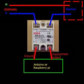
There are two approaches. The simplest is to use a relay and this can be done with the same circuit shown above. The relay has a small electromagnet which switches on/off a high voltage line. Asecond approach which doesnt have any mechanical parts is a solid state relay (SSR). These devices have built in semiconductors which does the switching and there is an isolation in the form of opto-couplers or so to isolate the low voltage arduino lines from the mains. These SSR can switch devices at 120 or 220 volts depending on the bulit and can be obtained from manufactures like omron also can be spotted on online stores like ebay.
 |
| Solid state relay to easily control ac 220v/120v devices with arduino |
Controlling AC fan speeds with arduino/raspberry pi
It is normal to think that the pulse width modulation can be used to control the speed / brightness of ac devices by pwm ing the SSR. But it is not feasible and a different approach is needed to adjust the motor speeds in AC. The lights can be controlled by converting AC to DC as they works on both while AC motors need some tricks to adjust their speed. This is done by controlling the on time of triacs after a delay from zero crossing (more details on this is beyond the scope of this post). A manual control circuit for AC fan speed is shown below
 |
| AC 220v ceiling fan speed control with arduino pwm trick |
But here is a trick with out the need for zero crossing and is borrowed from an article (dont remeber where) which used a similar approach on a drilling machine. See the modification above where a cds ldr is used in place of the variable resistor used to control the capacitors charging time and a pwm ed led is used to adjust the resistance value. This is a quick and dirty hack and may help some one. The correct way is complex and need to sense the zero crossing and the firing time of triac with respect to the ac cycles.
this is really helpful for me....Keep posting :-)
ReplyDeletehi,
ReplyDeleteI know this was written quite some time ago... I think the ULN driver chips is a much more elegant solution to replace the TIP-122. I have a problem - maybe you can help.
I have a clock cct Arduino driving a set of seven segment displays via current limiting resistors (470 Ohm) Common cathodes are all multiplexed via transistors.
I want to have large 12 inch seven segment displays (also common cathode) to be driven in a similar way from a 24v source on the seven seg displays.Any suggestions?
Regards
Zahir
same technique with a transistor switch on all the lines should work. Use appropriate current limiting resistor to match your display. If you like an ic , there is a simple solution with http://www.ti.com/lit/ds/slus171c/slus171c.pdf
Deleteأنا حسام الدين من سوريا عمري خمسين عام أحب أن أرى إبداعات الشباب في مجال الألكترونيات الجميل والراقي لأرى جمال الحياة من خلال إبداعاتهم مهما كانت بسيطه المسألة ليست في التعقيد أو البساطه ولكن المسأله أين ستصرف وتسخر مجالات الإبداع لأنه ومن المعلوم أنه خلال التاريخ الحديث كثير من النقلات والقفزات العلميه القويه صرفت وسخرت لغير صالح بني البشر فلذلك علينا أن نحمل في عقولنا وقلوبنا المعاني الساميه ومن بعدها لننطلق إلى الإبداع المثمر المفيد لكل من حولنا أرجوا لكم التوفق والنجاح الدائم
ReplyDeleteThanks for the wishes
Delete